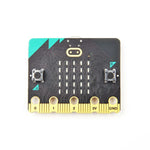
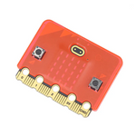
These ELECFREAKS IIC OLED Module are small, but very readable due to the high contrast of an OLED display. This display is made of 128x64 individual white OLED pixels, each one is turned on or off by the controller chip. Because the display makes its own light, no backlight is required. This reduces the power required to run the OLED and is why the display has such high contrast; we really like this miniature display for its crispness!
The OLED itself requires a 3.3V power supply and 3.3V logic levels for communication, but we include a 3.3V regulator and all pins are fully level shifted so you can use it with 5V devices!
FEATURES
OLED is self-luminous, with no backlight
Screen size: 0.96
Resolution: 128*64
Color: Blue
Communication method: IIC
Working temperature: -20-70
Operating Voltage: 3.3-5V
Module size: <27mm*28mm
PROGRAMMING
<syntaxhighlight lang="php">
- include <Wire.h>
// with no jumpers the full address is 1 0 0 1 1 1 1 0 0 A2 A1 A0 0x27 is the default address for the board with no jumpers.
- define PCA9555 0x27 // 0x27 is default address for the board with no jumpers.
// 0x20 is address for the board with all jumpers.
// COMMAND BYTE TO REGISTER RELATIONSHIP FROM PCA9555 DATA SHEET // At reset, the device's ports are inputs with a high value resistor pull-ups to VDD // If relays turning on during power up are a problem. Add a pull down resistor to each relay transistor base.
- define IN_P0 0x00 // Read Input port0
- define IN_P1 0x01 // Read Input port1
- define OUT_P0 0x02 // Write Output port0
- define OUT_P1 0x03 // Write Output port1
- define INV_P0 0x04 // Input Port Polarity Inversion port0 if B11111111 is written input polarity is inverted
- define INV_P1 0x05 // Input Port Polarity Inversion port1 if B11111111 is written input polarity is inverted
- define CONFIG_P0 0x06 // Configuration port0 configures the direction of the I/O pins 0 is output 1 is input
- define CONFIG_P1 0x07 // Configuration port1 configures the direction of the I/O pins 0 is output 1 is input
- define PAUSE 200
void setup() {
  delay(1000);
 display.initialize();
}
void loop() {
display.drawLine(0, 0, 127, 63,WHITE);
 display.update();
 delay(1000);
 display.clear();
 display.setTextSize(1);
 display.setTextColor(WHITE);
 display.setCursor(0,0);
 display.println("Hello, world!");
 display.setTextColor(BLACK, WHITE); // 'inverted' text
 display.println(3.141592);
 display.setTextSize(2);
 display.setTextColor(WHITE);
 display.print("0x"); display.println(0xDEADBEEF, HEX);
 display.update();
 delay(2000);
 display.clear();
}
</syntaxhighlight>


