Suppose you're using the Wukong2040 to develop an intelligent sensor system that needs to handle multiple tasks simultaneously: reading data from sensors, processing data for real-time analysis, sending data to the cloud via a wireless module, and responding to real-time control commands from users. Without an RTOS, you may need to write complex code or manually manage the execution of these tasks, which is tedious and error-prone, especially when the tasks are numerous and complex.
Is FreeRTOS suitable for the Raspberry Pi Pico's RP2040 chip? I wondered. As it turns out, it can, and here's how you can set up a very basic FreeRTOS project, which can also serve as a demonstration.
When I started exploring Pico projects and the application of FreeRTOS, I found that many existing blogs and example projects on GitHub/GitLab assumed the reader already had an in-depth knowledge of FreeRTOS. However, in this article, I have deliberately avoided this assumption. My goal is to make it easy for those who are just stepping into the world of FreeRTOS to follow along, not only understanding what we are doing but, more importantly, why we are doing it. By providing step-by-step explanations and clear examples, I hope to help every beginner smoothly get started and enjoy using FreeRTOS.
1.Advantages of FreeRTOS
FreeRTOS brings multitasking capabilities to embedded devices, similar to what you experience on a computer. Typically, embedded processors don’t run multiple applications, but their applications can benefit from running multiple tasks in parallel, just as a single application on a computer might span multiple threads. The operating system switches the processor between all these tasks or threads millions of times per second, giving the user the impression that they are working simultaneously.
Why structure Pico applications this way? Because the application may benefit from having one task run periodically and consistently to update the display and check user input, while another task only needs processor resources when there are numbers to process.
This ability to schedule multiple threads is very convenient for the RP2040, which has two cores available. Scheduling between RP2040 cores has been demonstrated in FreeRTOS, and once fully integrated, it will allow tasks to be automatically scheduled across both cores.
2.Building FreeRTOS Applications
A FreeRTOS project essentially involves compiling the operating system as a library and linking it into the final application binary. For Pico applications, the binary is the output from the linker, then used to generate the .elf and .uf2 files, which are copied to the installed board. ‘.elf.uf2’
FreeRTOS is configured using a standard file, FreeRTOSConfig.h, which sets up the OS to utilize the specific features of the chip it runs on. This file, along with some application code and CMake configuration files, forms the foundation of an RP2040 FreeRTOS application. Therefore, I’ve put them together as a project template. ‘FreeRTOSConfig.h’
3.Using Submodules
FreeRTOS and the Pico SDK are included as Git submodules in the template. This means the remote copy does not include all the source files for these projects, just references to them. You still need local code to build the application, so once you clone the template repository and jump to its directory, you need to run the command:
‘git submodule update --init --recursive’
Pull down the code, sets up the local repository records and ensures you download any submodules referenced by your submodules. Whenever you want to check and download updates for FreeRTOS and the Pico SDK, simply run the command again.

For Pico projects, adding FreeRTOS involves including FreeRTOS source files in the project file, which also pulls in and initializes the Pico SDK.
'FreeRTOSConfig.hCMakeLists.txt'
To clarify, I organize my project files and application source code in one folder, with the Pico SDK and FreeRTOS folders, and the top-level CMakeLists.txt file:
I also create a subfolder for the app, called from the main CMakeLists.txt file:
'CMakeLists.txtApp'

In setting up this project, part of the work involved spending time understanding CMake better and simplifying it. As seen in the snippet above, CMake supports variables, so I set up a lot of project-specific information early and reference it by variables in both files. This makes it easier to copy files for other projects:'CMakeLists.txt'
I included the Pico SDK in the template, but if you’ve already installed it elsewhere and set up and exported the environment variables, you don’t need to do this. The template’s main file is set to use the local SDK for its run, but you can disable this by commenting out the following line:'PICO_SDK_PATHCMakeLists.txtPICO_SDK_PATH'
Beyond that, the main file sets some project-specific variables, imports, and initializes the SDK. Next, it adds the FreeRTOS source files as a static library, which links to the application during the build:'CMakeLists.txtpico_sdk_import.cmake'
Adding the key FreeRTOS directories triggers the loading of the OS's own files:
'CMakeLists.txt files'
Finally, I add directories to load and process its own files. What's in these files? They compile the application source code files and then link to the compiled SDK and FreeRTOS libraries:'AppCmakeLists.txt'
4. Device Installation Script
I wrap all this up with a shell script, which takes the build file path and transfers it to an RP2040-based board. If you include the flag, it will compile the code for you as well.'deploy.sh.uf2--build'
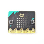
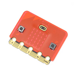
To test this project, I used the Wukong2040, a new development device based on the RP2040. Like many recent Pico clones, it includes both a BOOTSEL button and a RESET button, making it much simpler to load new application code than using a Raspberry Pi board. Instead of holding BOOTSEL and reconnecting the USB cable, you hold BOOTSEL, click RESET, and release BOOTSEL. The RP2040-Plus immediately reboots into code loading mode without needing to fiddle with the cable.
‘deploy.sh’ will wait 30 seconds and copy the compiled and linked files as soon as the standard volume is mounted on your machine. '.uf2RPI-RP2'
5. Demonstrating the Application
Finally, let's take a quick look at the application itself, located in `.App/main.c`.
This application blinks two LEDs: one is built into the board, and the other is connected to GPIO pin 20. Using FreeRTOS for this task might seem like overkill since you could achieve the same result with just a few lines of code. However, it does showcase some key FreeRTOS features.
The key lines in `main( )`
These names are mainly for debugging purposes. Each task is allocated a stack of 128 words—i.e., 512 bytes for the 32-bit RP2040—which is more than sufficient for this application, and assigned a priority of 1. This is a mandatory setting when FreeRTOS is configured to provide memory allocation, as specified in `FreeRTOSConfig.h`.
Next, the code creates a queue that will be used to pass messages (data) between the two tasks. The queue has a depth of four entries, each entry being one byte in size.
Finally, the code calls to tell FreeRTOS to start running the specified task. These tasks are implemented as functions - a pointer to each task is passed into the call to 'vTaskStartScheduler()xTaskCreate()'.
The first task function, configures the GPIO pin for the internal LED and turns it off. The code also uses each time you change the state of the LED. You do not add a value directly; instead, you provide a reference to a variable that stores the value. 'led_task_pico()xQueueSendToBack()'
`vTaskDelay( )` is used to pause the task for a period of time, specified in milliseconds, calculated from internal ticks:
The second task function, configures an LED on GPIO pin 20 and then does nothing but call to see if there is a new message on the FreeRTOS queue. If so, it copies that value into the memory specified as a pointer. This is a byte that indicates the state of the board's LED, so we simply set the LED for this function to the opposite of that byte.
'led_task_pico()xQueueReceive( )'